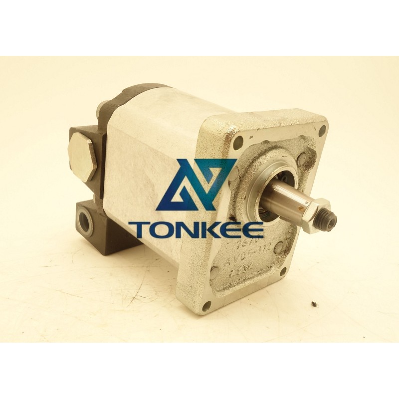
Flow Rate: The pump has a maximum flow rate of 5 gallons per minute (GPM), making it suitable for a wide range of applications.
Operating Pressure: It can handle pressures up to 2500 pounds per square inch (PSI), which is sufficient for many hydraulic systems.
Mounting: The pump is typically designed for SAE-B 2-bolt mounting, ensuring easy installation and compatibility with various systems.
Material: It is commonly constructed from durable materials like cast iron or aluminum, depending on the specific application requirements.
Drive Shaft: The pump features a standard spline drive shaft, which connects to the prime mover (usually an electric motor or an internal combustion engine).
Components:
The 5B1 40103BOS hydraulic gear pump consists of several essential components:
Housing: The pump's outer shell, typically made of cast iron or aluminum, provides structural support and contains the internal components.
Gears: This pump uses two interlocking gears - a driving gear and a driven gear - to create a positive displacement, pushing hydraulic fluid through the system.
Inlet and Outlet Ports: These ports allow hydraulic fluid to enter and exit the pump. Inlet ports are connected to the reservoir, while outlet ports send pressurized fluid to the hydraulic circuit.
Seals and Bearings: To ensure efficient operation and prevent fluid leakage, the pump incorporates seals and bearings in various locations.
Working Principles:
The operation of a hydraulic gear pump is based on the principle of positive displacement. As the driving gear rotates, it meshes with the driven gear, creating pockets that trap hydraulic fluid. As the gears continue to rotate, these pockets decrease in size, forcing the fluid out under pressure through the outlet port. The continuous rotation of the gears ensures a steady flow of hydraulic fluid, which is essential for powering hydraulic actuators, motors, and other components in the system.